Thursday, October 1, 2015

Disc Couplings - Failure Analysis (Part 3)

If history is any judge, this post will be by far the most popular in our mini-series of three blogs on disc couplings. The first post provided a broad overview of disc couplings, and the second posts covered a number of key terms used when talking about disc couplings... but this third post is on the riveting topic of disc coupling failures.

To date, the Coupling Answers blog posts coupling failures (including Jaw Coupling Failure Analysis , Gear Coupling Failure Analysis, and Grid Coupling Failure Analysis) have been extremely well-received and appreciated by our amazing customer base. One of the reasons these posts have been so well received is that so few people like to talk about failures. Fortunately, we at Lovejoy, are confident enough in our products, design capabilities, and general understanding of power transmission that troubleshooting isn't something we shy away from. (In fact, for Hannover Fair 2015, we actually hosted a Coupling Solutions Learning Lab that was loaded with actual failed couplings. This caught countless German engineers completely off-guard.)  Moving on...


Misalignment Failures


Disc Coupling Failure - Misalignment
Misalignment Failure
Like many other coupling types, disc couplings often fail in with telling or "signature" ways that point to a likely culprit. As pictured at right, when a disc coupling is subject to excessive misalignment it is likely to experience disc pack cracking near the bushings, with the outer layers fracturing first.

Disc Coupling Pack Failure - Misalignment
Misalignment Failure
Note: Given disc packs generally crack from the outer layers in, it is certainly possible that a coupling will continue to transmit torque/function with cracks in the outside layers. This means that it is still important to inspect the disc pack on a periodic basis even if the coupling appears to be functioning properly. Fortunately disc packs can generally be inspected without disassembling the coupling, and possibly even when the coupling is running (by using a strobe light assuming the coupling guard is not solid steel).

If misalignment is the likely source of a disc pack failure, it is important to realign the coupling prior to restarting the system, less the issue repeat itself. (Two options to consider when realigning a coupling are laser alignment and dial indicators.) An additional step you can take if you are not using a scalloped disc pack by Lovejoy (which offers increased misalignment handling over legacy designs), you can source a replacement coupling from us!
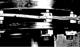
Disc Coupling - Misalignment Failure
Misalignment Failure

Torque Overload Failures

Disc Coupling Torque Overload Failure
Disc Pack Torque Overload Failure

Torque overload failures in disc packs look different from misalignment failures in that the fatigue cracks tend to form in the center of the disc pack rather than up against the bushings (as pictured at right).

A second thing to look for when suspecting torque overload on this disc pack is any evidence that the disc pack layers (or laminates) are separating or ballooning away from each other in the center sections between bushings.

Distorted Disc Coupling Bolts
Bent Disc Pack Bolts
 In addition to the disc packs themselves, the bolts used to connect the disc pack to the flanges may be bent or distorted. Such distortions are another excellent indication that the coupling is seeing torque in excess of what it was designed to handle. 

Disc Coupling Hub Burst - Overload Failure
Disc Coupling Hub Burst
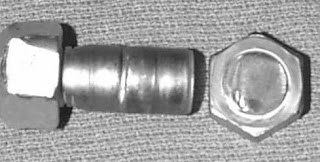
A third and final common way that torque overload reveals itself in a disc coupling is if a coupling hub actually bursts over the corner of the keyway. This is a failure mode common across many coupling types, and the reason the coupling fails at this point is because, due to the cut keyway, this is the weakest point in the hub.


Installation & Fastener Failures


One of the fastest way to damage a disc coupling during installation is to use impact wrenches. (Do not do this!) Not only does using an impact wrench raise the potential of twisting the disc pack (pictured at right) in a destructive manner, but it also raises the possibility of friction welding the fastener bolts to either the disc pack and or the connected flange. Fasteners should be lubricated prior to installation and torqued with care.

Twisted Disc Pack InstallationTwisted Disc Pack Installation - Close Up

On the other end of the spectrum, improper torque of the fasteners may cause them to loosen. This loosening can then lead to damage and wear to the fasteners as well as hole elongation and cracking of the disc packs. To avoid either over or under torquing the fasteners, be sure to read and follow the disc coupling's installation instructions. (Lovejoy's disc coupling installation instructions and videos can be found here.)

Disc Coupling - Fastener Failure Disc Coupling - Fastener Wear


Disc Coupling - Disc Pack Elongation Disc Coupling - Bolt Failure and Hole Elongation

Environmental Failures


Corroded Disc Coupling Disc PackWhile disc couplings generally hold up very well to many environmental conditions, they are certainly not impervious to everything. As such, it is critical that coupling users understand what corrosive agents may be present for a given application, and that the disc coupling is designed to operate under those conditions. (Pictured at right is a circular, non-scalloped, disc pack layer that has been corroded.) 


Life Expectancy


Having just covered misalignment, torque overload, installation, fastener, and environmental failures of disc couplings, a natural question might be "How long is my coupling going to last?" Unfortunately, like all other coupling type, disc coupling life is not generically predictable as it is highly dependent upon the application and the misalignment of the given system it is driving. Shaft alignment does correlate strongly with longer coupling life... so taking the time to align the system properly with periodic checks should pay lasting dividends and not be overlooked.

To learn more about Lovejoy's disc coupling solutions for your applications, please check out Lovejoy's disc coupling product pages & catalogs, the non-lubricated section of The Coupling Handbook, and/or pick up the phone ask to speak with a Lovejoy application specialist.

Monday, September 28, 2015

Disc Couplings - Common Terminology (Part 2)


Design Basics - Common Terminology

DI Style Disc Coupling - by Lovejoy, Inc.
DI "Drop-Out" Type Disc Coupling
The diagram of an industrial DI Type "drop-out" style disc coupling at right highlights a number of useful terms common in describing a disc couplings.

(Note that because this coupling has two disc packs, it is equipped to handle parallel in additional to angular misalignment. It is for this reason that many disc coupling designs make use of two disc packs, and not just one.)

"Hubs" are the metal element designed to attach to the two shafts of a power transmission system.

"BSE" stands for "Between Shaft Ends" and describes the specified distance between to two shafts that the coupling is design to connect.

"PW" describes the space allocated for the each disc pack.

The "Spacer Assembly" is called out specifically in this design as the whole center section of the coupling, including the two disc packs, is designed to be able to be removed from an installation with requiring the coupling hubs to be moved or removed. A drop-out spacer assembly section, as shown in the image above, is an additional feature not common to all spacer disc couplings. An example of a spacer disc coupling without a drop-out assembly section would be Lovejoy's SX Type.

In the case of Lovejoy's DI Type disc coupling, "Guard Rings" are included and hubs are piloted to ensure proper centering of the drop in spacer assembly. This piloting serves as an anti-flail feature and aids in the couplings ability to meet API 610 requirements.

SX Type Disc Coupling with SLD
While disc couplings commonly use interference fit hub-to-shaft connections, another hub-to-shaft connection feature available for disc couplings are shaft locking devices ("SLDs").  As shown in the photograph at right and the installed photograph below, shaft locking devices allow pressure to be exerted on a hub to connect the hub firmly to a shaft for torque transmission. The advantage of using shaft locking devices is that users can avoid interference fits that require significant maintenance time to remove. The disadvantage of shaft locking devices is the initial upfront cost. Additionally, watching tolerances and understanding the ratings of a shaft locking device are also critical as the shaft locking device may have ratings below the coupling and or system requirements. 


To learn more about disc couplings, please check out Part 1 of this blog series... or Lovejoy's disc coupling product pages & catalogs, the non-lubricated section of The Coupling Handbook, and/or subscribe to this blog as there will be several more blog posts on disc couplings in the immediate future.

Thursday, September 24, 2015

Disc Couplings – General Overview (Part 1)

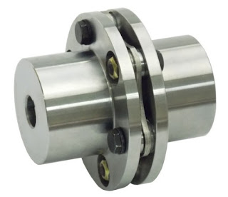
Single Disc Pack SU Type Disc Coupling by Lovejoy, Inc.
A Single 6-Bolt Disc Pack SU Type Disc Coupling
Disc couplings are a popular coupling design that continues to pick up steam within the power transmission industry in large part because they can transmit a significant amount of torque, while also being minimal maintenance. Unlike lubricated gear and grid couplings, disc pack couplings require no lubrication and periodic re-lubrication. This makes them ideal for applications that are hard to reach or get to... which, given increased maintenance department budget constraints... is broadly appealing across countless high torque applications and industries.

Unitized Disc Pack Profile
Disc packs can be visually inspected without taking apart the coupling (a major time savings not true with gear or grid couplings) and have "theoretical infinite life" in that they have no wearing metal-on-metal misalignment handling flex points (as is the case with lubricated gear and grid couplings). Rather, misalignment handling occurs through the flexing of unitized disc packs connecting two flanges together. Should a disc pack wear out (generally due to fatigue brought on by excessive misalignment), bolts and the unitized disc pack can be generally removed and replaced without having to move the installed coupling hubs.

Furthermore (yes.. there are a lot of positives with this coupling type), generally being all metal (with no seals or gaskets) gives disc couplings the ability to withstand harsh environments.. And, lastly, to give one more potential major benefit (based on the application) over their lubricated brethren, disc couplings have torsional rigidity with no backlash.

Limitations of disc couplings include no vibration dampening capability (a strength of elastomeric & grid couplings), and limited misalignment handling capability... particularly in regards to parrallel misalignment. (For a disc coupling to handle parallel misalignment, two disc packs must be used.) Additional considerations include speed limitations if not balanced (though these can be overcome as evidence by widespread disc coupling usage in API 610 and API 671 applications), and possible anti-flail concerns (though, again, anti-flail safety features can be added to many designs).

Design Basics  - Disc Packs

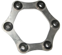
Six Bolt Unitized Disc Pack - by Lovejoy, Inc.
Six Bolt Unitized Disc Pack
Disc couplings and their disc packs are generally referred to by the number of bolts they have. Common bolt configurations include 4 bolt, 6 bolt, & 8 bolt. The reason bolt configurations are even is that torque is only carried in tension across every other leg of a disc pack (while the remaining legs will be in compression). In a 4 bolt design, 2 legs will be carrying the torque. In a 6 bolt, 3 legs... and, in an 8 bolt, 4 legs.

The trade-off between the number of bolts is torque versus misalignment handling capability. More bolts (and more legs sharing the load) can carry higher torque loads, but this increase also decreases the flexibility of the disc pack and ability of the pack to handle increased misalignment.

Eight Bolt Unitized Disc Pack - by Lovejoy, Inc.
Eight Bolt Unitized Disc Pack
Shown at right are both six bolt and eight bolt designs. In both cases, the unitized disc pack has a scalloped design. This scalloped design is a design enhancement over earlier disc pack designs, which had circular or straight sides. By eliminating the excess material around the outside diameter of disc pack from earlier designs, the scallop eliminates a prior source of peak stress within the disc pack and allows the disc pack to accommodate more misalignment. (Note: All of Lovejoy's disc couplings leverage an advanced scalloped design.)

Disc packs are generally made of thin layers of stainless steel (though materials can vary) that have been "unitized" into a single easy to handle/install/replace unit by use of bushings. Some early and current designs styles still make use of non-unitized layers, which can be a bit trickier to deal with from a maintenance and handling perspective. (Note: All of Lovejoy's disc couplings leverage a unitized design.)    

As illustrated in the diagram of the 6 bolt disc pack below, fasteners are then used to connect the disc pack bushings to the coupling flanges. For each bushing location, the disc pack will be connected to only one of the two coupling flanges and the flange it is connected to will switch back and forth as you circle around the disc pack in either direction. 
Disc Pack Bushings Fasten to Alternating Flanges

To learn more about disc couplings, please go to Part 2 of this blog series... or check out Lovejoy's disc coupling product pages & catalogs, the non-lubricated section of The Coupling Handbook, and/or subscribe to this blog as there will be several more blog posts on disc couplings in the immediate future.

Tuesday, September 22, 2015

Proud to be "Mobile Friendly"!

Lovejoy Website - Mobile Friendly
It may have taken us a bit longer that we had hoped, but we are still very excited to share that our Lovejoy website (www.lovejoy-inc.com) is now "mobile friendly" for all our smart phone users out there!

Unlike this blog, which was started long after "mobile friendly" became a hot topic... and was "mobile friendly" since inception, the Lovejoy website was built on a platform long before mobile friendly was of primary concern).

As such, recoding the site to be "mobile friendly" was both labor and cost intensive... but we recognized the value being mobile friendly was for our dedicated users base (especially those out in the field looking to access a key dimension or installation guideline) and committed the necessary resources.

If you happen to be viewing this blog on a mobile device, we certainly invite you to head over to our main website to have a look around. If and when you do, please leave us a note about what you liked and/or what you would like still improved. (Your satisfaction is our #1 goal!)

Monday, September 21, 2015

Frankenstein Couplings - Unique Configurations, Materials, and other Oddities

With Halloween just over the horizon, we thought it would be worthwhile do write a blog post on something Lovejoy is particularly well renowned for: Frankenstein couplings!

What exactly is a Frankenstein coupling? It's a one-off, highly customized or unique coupling that most coupling manufacturers run away from.

Fortunately, given Lovejoy's tremendous depth of product knowledge, experience, and local manufacturing capabilities... such couplings are standard practice for us, and these are opportunities that we readily welcome.

In fact, our reputation is such that, while they might not like to openly admit it... other well-respected marketplace players have been known to send such business our way.

So... to borrow the lyrics of Ghostbusters:

Ghostbuster Halloween Cut imageIf there's somethin' strange in your neighborhood, who ya gonna call? (Lovejoy Application Engineers!)

If it's somethin' weird and it won't look good, who ya gonna call? (Lovejoy Application Engineers!)

From the most exotic materials (Inconel, Specialty Stainless Steels, Composites, etc.) & head-scratching unique configurations...to our tremendously deep lineup of "standard" off-the-shelf solutions, Lovejoy's team of Application Engineers and Specialist are on standby to help you and your organization succeed.

We look forward to being a growing resource for you, and wish you nothing short of the happiest Halloween ever!

Friday, August 14, 2015

What is the difference between a spacer vs non-spacer coupling?

Flexible couplings can serve a multitude of purposes in a power transmission system, but the two most primary are connecting two shafts (so that torque can be transmitted)and accommodating misalignment between these two shafts (to allow the system to operate more optimally and extending system life). 

Couplings are generally designed to handles a specific range of separation between the two shaft ends, typically referred to as the "BSE" (Between Shaft Ends) measurement. "BSE" measurements for a specific coupling can usually be found within a given manufacturer's catalog (which we hope would be one of ours!)

Spacer vs Non-Spacer CouplingsTo increase the flexibility of a coupling to handle larger BSE situations, spacers can be added to a coupling design. Furthermore, by leveraging a spacer design with flexing elements on each side of the spacer, a coupling can generally be expected to be able to handle more misalignment as that spacer component grows longer.  As a third benefit, spacer designs can also be designed to be "drop-out" making for easier system maintenance and repair. 

Pictured at right are three diagrams of disc couplings found in Lovejoy's disc coupling product offering. The first, the SU Type, leverages a single disc pack and two hubs. There is a single flexing element, and the "BSE" range is fairly limited. The second, the SX Type, incorporates two flexing elements and a center spacer element. This spacer element can be extended or shortened based off of a users unique "BSE", while the hubs and disc packs can remain common to the SU Type design. The third coupling shown, the DI Type, allows for the entire disc pack spacer assembly (comprised of the spacer, 2 disc packs, and 2 guard rings) to be removed from a system without being required to remove the hubs or push back any other pieced of equipment.

Whether a coupling is a "spacer" or "non-spacer" design does not describe the type of flexing element being incorporated into the design. Elastomeric couplings (such as Lovejoy's L-line or S-Flex) and metallic couplings (such as gear, grid, and disc - shown above) are all offered as core "non-spacer" designs, but are also available in standard and custom spacer varieties. 

While there are many benefits to spacer designs, they also do have several important detractors. First, you are adding material and complexity, so the cost of the coupling will generally be higher as the "BSE" requirement grows. Also, as the "BSE" requirement grows and material is added, weight is also generally added to a system. This overhung load can lead to increased load on the systems being coupled (potentially generating excessive loads on bearings, etc.). Where spacers become long and weight becomes an issue (i.e. - cooling towers), spacers traditionally made out of hollowed out steel can be replaced with carbon fiber or composite tube spacers, though this change will add further cost to the overall coupling solution. 

Should you have any further questions on spacer or non-spacer couplings, or should you have an application you would like us to quote... please do not hesitate to contact Lovejoy's application engineers at 630-829-1515 from 7am to 5pm Central Standard Time. (For additional contacts, or more product information... please visit our corporate website.)

Friday, July 24, 2015

Chain and belt tensioning

RunRight Belt Tensioner - by Lovejoy, Inc.
Belt tensioning with RunRight tensioner
Chains and belts are both naturally prone to stretching, and… if proper tensioning is not maintained in a system… a number of issue may present themselves, inclusive of suboptimal operation, premature system wear, and, ultimately, system failure. 

RunRight belt tensioner - by Lovejoy, Inc.
Belt cleaning with RunRight tensioner
Designed specifically to provide economical, maintenance-free, continuous tensioning for belt and chain drive systems... for almost any application... Lovejoy’s full line of RunRight® tensioners are up to the challenge. 

Tensioners are available from stock in seven sizes (SE11, SE15, SE18, SE27, SE38, SE45, & SE50) and a number of mounting configurations (standard, front mount, double arm, dual arm, stainless steel, plastic...) to handle a wide range of load demands and environmental conditions. 

System Tensioner - by Lovejoy, Inc.
Providing tension on production products
Most tensioners are also equipped with a two mounting holes: a "normal" and "hard" position to offer further system optimization. 

In depth product catalogs are available on Lovejoy's website. Should you have any further questions or concerns regarding this product line, please do not hesitate to contact a Lovejoy application specialist.

Related Posts Plugin for WordPress, Blogger...